


1. Protocols and frequencies
Wireless protocols and operating frequencies Antennas are defined by the protocol they function for, examples include Bluetooth/Wi-Fi, GNSS, cellular network, ultra-wideband, ISM and NFC. The various protocols correspond to different operating frequencies. For example, Bluetooth antennas operate within a frequency range of 2.4 to 2.485GHz, while NFC antennas operate under a frequency of 13.56MHz. Even within
the same protocol, various frequency bands are allocated. To select the most suitable antenna, users must define both the protocol and operating frequency.
2. Types
Antennas come in different forms and shapes, and what is ultimately selected depends on a consideration
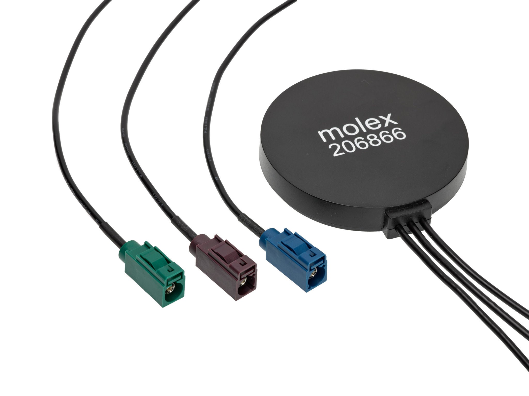
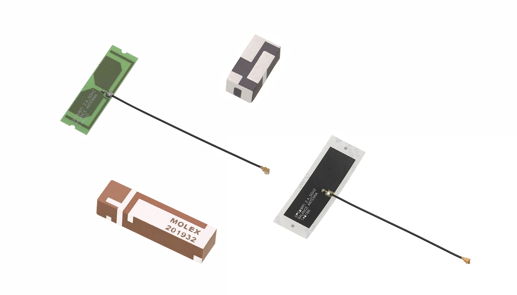
of customer preferences and usage environments. Based on their materials and processes, they can be categorized as a PCB, SMT, FPC, ceramic and external rod antenna. For example, to solder an antenna to the PCB, a surface mount antenna is most appropriate. FPC or PCB antennas can be options when the antenna
is to be placed on the interior wall of the housing and the connection is through an RF connector, while an external rod antenna is likely when the antenna is to be placed on the outside of the product. But because an antenna’s transmission capabilities are very sensitive to its surrounding environment, for optimal results, it is best to determine its position before selecting the type.
3. Sizes
An antenna is designed according to the needed wavelength/frequency of operation. Antennas with sufficient wavelength will perform better than antennas with sub-optimal wavelength. For the best wireless performance, users should choose a bigger antenna if the size of the product permits.
4. Balance
An in-balance antenna is smaller in size, but it uses the PCB grounding as part of the antenna system, whereas a balanced antenna can function by itself although it is bigger. If the size of the product permits, it is better to choose a balanced antenna. If this is not possible, choose an appropriately sized PCB grounding.
5. Performance indicators
The performance of an antenna depends on several indicators, such as impedance, efficiency, S11/VSWR, radiation pattern, gain, polarization and axial ratio.
a. Impedance
An antenna’s impedance needs to align with the output impedance of the wireless module, which is generally 50 Ohms.
b. Efficiency
Antenna efficiency is a key indicator that determines the emissivity of an antenna.It specifies how much energy will be lost during the energy exchange. The greater the efficiency, the better the antenna is. Generally, a value greater than 40% indicates acceptable performance.
c. Return loss (S11) and voltage standing wave ratio (VSWR)
S11 or VSWR indicates the amount of energy reflected in the RF circuit and transmitted to the antenna. The smaller the value, the better it is. Generally, S11≤-6dB or VSWR≤3 would indicate acceptable performance.
d. Radiation pattern.
An antenna’s radiation pattern shows how the antenna radiates in a 3D plane. The radiation pattern depends on the type of antenna and the surrounding environment. If the radiation pattern is tested under a scenario with free space (no surrounding interference), it might not represent the real situational pattern as It will change per environment due to reflections and loading. The pattern will show where and how the gain (described below) is distributed in the 3D space, indicating the strong and weak angles.
Depending on the application, a user needs to select an antenna with an omni-directional or a single directional pattern. Omni-directional antennas tend to be better for general purposes, while a directional antenna would be better for GPS or similar applications.
e. Gain (average and peak).
Antenna gain can be deemed as average gain or peak gain. The average gain is the average of the gain at a frequency across all the angles in the 3D space while the peak gain is the maximum gain at that frequency. The average gain is equivalent to the efficiency and the higher the better. A rounded antenna radiation pattern will have lower peak gain compared to a directional antenna. As with respect to radiation patterns, peak gain will be different in free space and when mounted on the device.
f. Axial ratio
Axial ratio is an important performance indicator for a circularly polarized antenna and represents its purity. Generally, an axial ratio smaller than 3dB indicates good performance.
6. Matching networks
The matching network is designed to optimize the antenna impedance to match 50 Ohms. For an acceptable S11/VSWR of the antenna, some antennas will be required to have a matching circuit. This is normally specified in the application guide. The application guide also references many other guides to achieve optimized antenna performance.
Once the above procedures are completed, the requirements for the antenna become clear. Such requirements are summarized per Table 1 below. The table can then be used to search for an antenna from
the product library of an antenna manufacturer. The Molex antennas are shown in Table 2.